Mechanics and Integration
Mechanical integration, system constraints and powering considerations.
Powering (general)
Modern particle detectors aim for large solid-angle coverage and high granularity, while requiring fast read-out, low power consumption, and a minimum of passive material inside the active region. Trackers are typically built from many identical modules that can be individually optimized.
The conventional scheme is parallel powering of modules with a constant voltage, enabling independent operation. For large-scale pixel detectors, however, low voltages and high currents over long cable runs can make cable losses comparable to (or larger than) the module power itself, while increasing service material.
Serial powering (general)
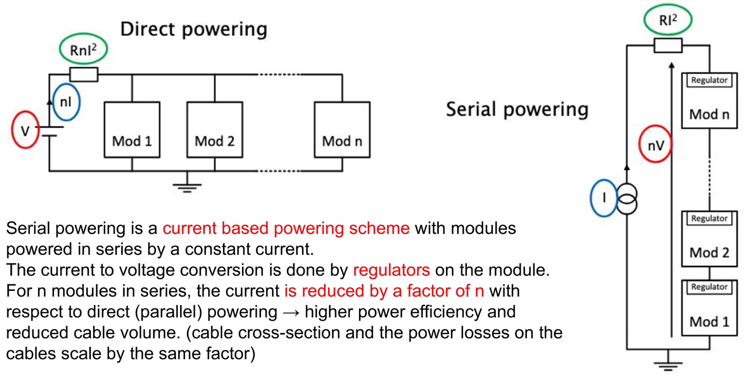
Serial Powering (SP) powers a chain of modules in series using a constant current. Only two power lines per chain are needed (instead of two per module). Voltages are generated by on-chip shunt and linear regulators.
- Fewer power lines → lower material budget in acceptance
- Reduced resistive losses → improved power efficiency
- Less heat in services → mitigates uncontrolled heating of nearby systems
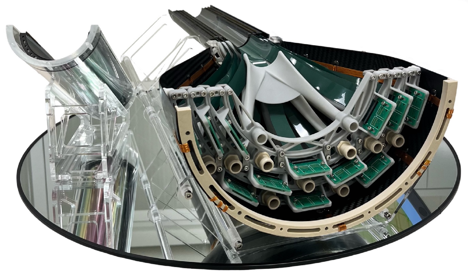
For the ALICE 3 Outer Tracker, serial powering is the baseline option, driven by the detector scale (≈60 m2 of MAPS), long staves, strict material constraints, and air-cooling requirements that motivate low power densities.
Linear vs shunt LDO
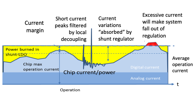
In practice, both are needed. A linear regulator provides a stable, low-noise voltage for analog and digital domains, but it cannot sink current. A shunt regulator acts as a controlled current sink to burn off excess current and keep the chain current constant—protecting downstream modules when load current drops.
Data links in serial powering chains
In an SP chain, modules sit at different local ground potentials. This makes AC-coupling mandatory for data links. Without it, the LVDS common-mode voltage can shift outside receiver limits for upstream modules, degrading link integrity and risking damage.
With AC-coupled termination, capacitors block DC components and the receiver sets the common-mode level. This requires a DC-balanced signal (e.g. clock) or an encoding (e.g. Manchester or 8b/10b) for command/data to ensure frequent transitions.

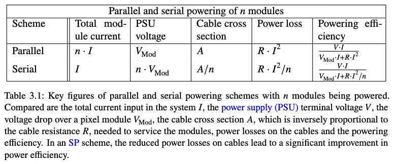
Parallel vs serial: key figures
Comparing total current, supply voltage, cable cross-section and losses shows why SP can significantly improve power efficiency and reduce service material—depending on how dominant services are in the overall power budget.
Header image placeholder
Replace the top image by overwriting:
assets/img/its3_expo.jpeg
You can also use .jpg or .png — just update the filename in page4.html.
- Constant-current chain
- On-chip shunt + LDO
- Headroom current
- AC-coupled LVDS links